Can not obtain good VSWR on 440 but the 2m gain is outstanding about 6dbd worth EXPERIMENT create you own unique designs the J is a very forgiving yet robust and. Tool Free Design for easy in-field adjustments.

J Pole Antenna Design Calculator By K4abt
Simple J-Type 10m Vertical by W6IOJ Sept.

. You will then need an antenna analyzer or a VNA to measure SWR and do trimming and adjusting 12 Step 1 Modify the Bracket Drill out the outer-most hole on one end with the 12 drill bit Drill out the middle hole next to the 12 hole just made with the 38 drill bit Remove the label on the bracket cleanly for a good electrical connection 13. 9 Simple J Pole Antenna Projects. J-Pole_Antenna-Designerphp 8271 Bytes 12-02-2018 112238 J-Pole Antenna Calculator.
Frequency MHz Wavelength mm Distance A mm. The radiating element of this antenna must be clear of nearby metal objects by. Enjoy low prices on earths biggest selection of books electronics home apparel more.
Its basically an end-fed omnidirectional half-wave antenna matched to the feedline by a quarter wave transmission line stub. Ad Browse discover thousands of brands. This antenna can be rolled up for easy portable use and will outperform a rubber ducky.
Intended physical length allowing a J-Pole antenna with a radiating section physically lengthened to 58-wave 49 inches to actually be radiating over a considerably longer length therefore radiating most of its power at useless higher angles and causing it to fall considerably behind the classic half-wave J-Pole design in performance. The antenna is en-closed in UV-resistant PVC pipe and can thus withstand the elements with only the antenna connector exposed. Lightweight durable and UV-resistant.
440 Super J-Pole Antenna by KA0NAN April 1996. Read customer reviews find best sellers. The Tri-band J-pole by KB6EPO III.
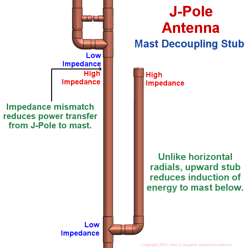
Invented by the Germans as Balloon Antennas and originally. This is important because if the mast extends above the antenna ground plane it will affect the performance of the antenna. The J Pole antenna is a popular antenna design among amateur radio operators because it is effective and easy to build.
Antenna Lengthis usually described as wavelength WL in meters or degrees. Microstrip Patch Antenna Calculator. The basic configuration of the ribbon J-Pole is shown.
This picture shows that the base of the antenna is mounted flush to the top of the mast. Parts needed 10 ft of ½ copper pipe 3 T Fittings 3 M to F 90 degree elbow fittings 1 reducing fitting 3 feed lines of 50 ohm coax V. Looking for a design for a 270 antenna I came across this one1 Whilst a lot of people have come across a single band J-Pole The original antennae for GB3TR were J-poles constructed from 300 ohm ribbon cable and housed in 40mm plastic wastepipe I had never seen a dual band example.
On most of the J Pole designs out there a choke should be used as close to the feedpoint of the antenna as possible to help prevent rf on the feedline and creating difficulty with SWR readings. To make our decoupling loop for the 6 meter J-pole lets use a length of the same type coax that we use as the feedline. This one looked particularly easy to construct with no.
J-Pole Antenna Plans printable PDF format800 kb This is a flexible antenna that is easy to build inexpensive and very handy to have in your emergency communications kit. We do this near the point where it connects to the antenna see figure 2. Make a five 5 turn coil 4 turns for 2 meters five 5 inches in diameter and tape it to J -pole mast below the feed points.
Inside spacing dimensions are metal to metal measurements NOT center to center. Up to 24 cash back tional single band ribbon J-Pole design to dual-band operation. Note 688 Yagi Uda Antenna Designer RothammelDL6WU Filter Designer Audio AF.
Get full performance in minutes. The antenna plans includes design. 34 inch copper pipe 165 inches 13 ft 9 inches 34 inch stainless steel hose clamr attach center conductor of coax cui and at 14 mc from of 3410 rrsecr10n fix antenna to mast 2 inch hose clampy u bolts may crimp copper pipe hose clamps secure well in my note.
For 2 meters the coil is 4 turns of coax at 5 inches in diameter. I have had this antenna on my roof since 1992 and it has been problem-free in the San Francisco fog. Benefits - Ground plane independent - Simplicity - Built in triplexer effect 3 feed lines - Simultaneous transmission - No Bleed over between bands - Assumed gain.
Ad Great for portable use while traveling camping and more. A J-pole antenna K4KRW Collinear J-Pole Bob K9TMUs Slim Jim Variation on J-pole dual band easily built from a piece of 450 ohm ladder line Commercial collinear base antennas multiple ⅝ wave elements means more gain lower takeoff angle watch out for overstated gain figures Diamond X-50a Ringo Ranger II Antennas for HF base use. 90 180 360 TIME λ2 180 λ4 90 ANTENNA LENGTH 1 WL meters Lambda λ 300 F MHz 5 VERTICALS Basic Vertical Monopole Radiation Resistance Radiation Resistance Rrad is that portion of the antenna input resistance that radiates power.
Yagi Uda Antenna Designer NBS Tech. Copper Dual-Band Super J-Pole Antenna by KA0NAN April 1993.

Pdf Modified Fractal Super J Pole Antenna

Pdf Analysis Of J Pole Antenna Configurations For Underwater Communications Semantic Scholar
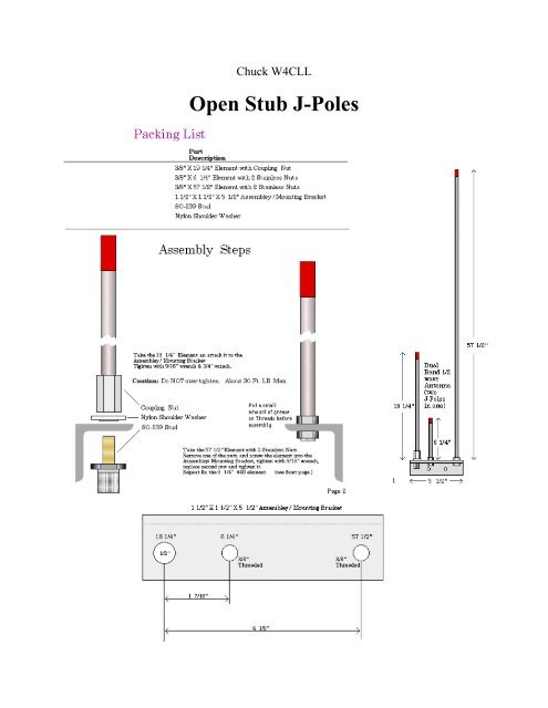
Open Stub J Poles Cascade Amateur Radio Society
Dual Band Vhf Uhf Twinlead J Pole Antenna Pdf Notes 201903101154 1
Antenna Types J Pole Antenna Design
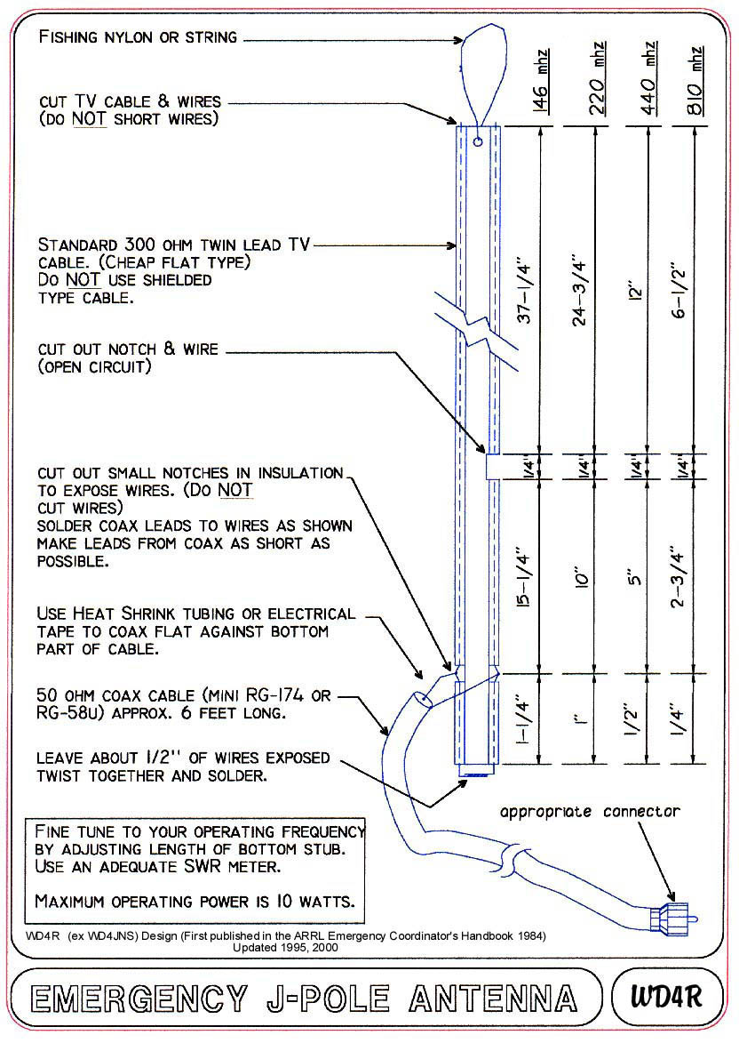
Emergency J Pole Antenna
Mast Mountable J Pole Antenna
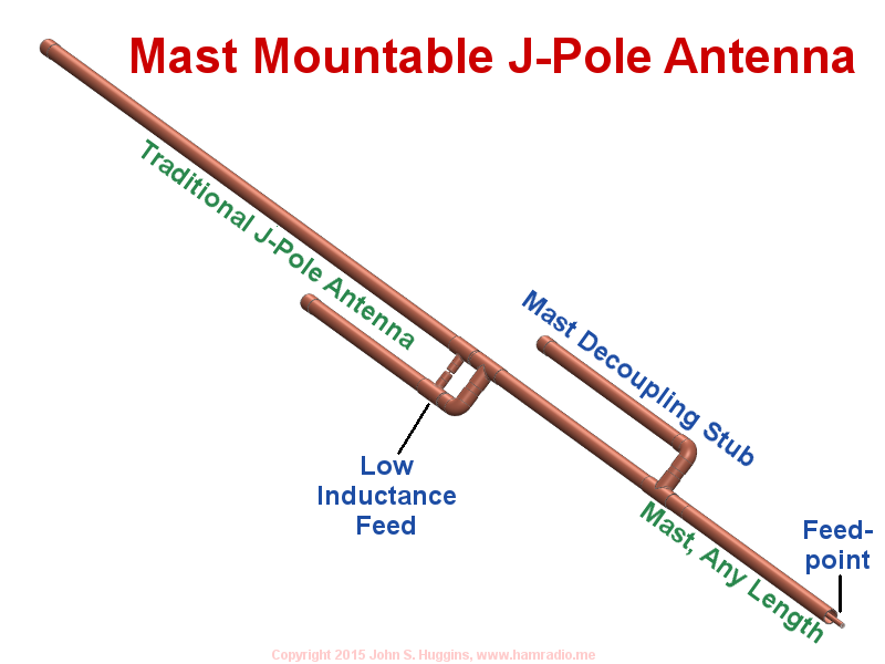
Mast Mountable J Pole Antenna
0 comments
Post a Comment